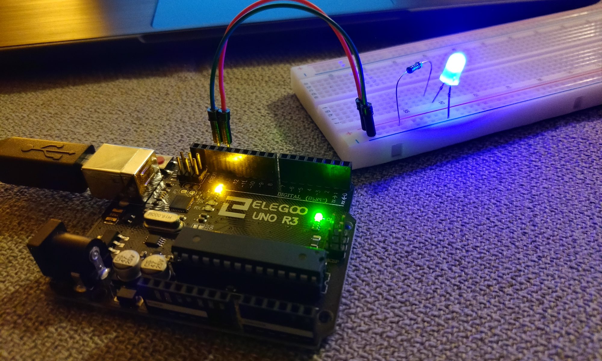
Ready to start hooking stuff from the kit up to your board and making them do things? Great!
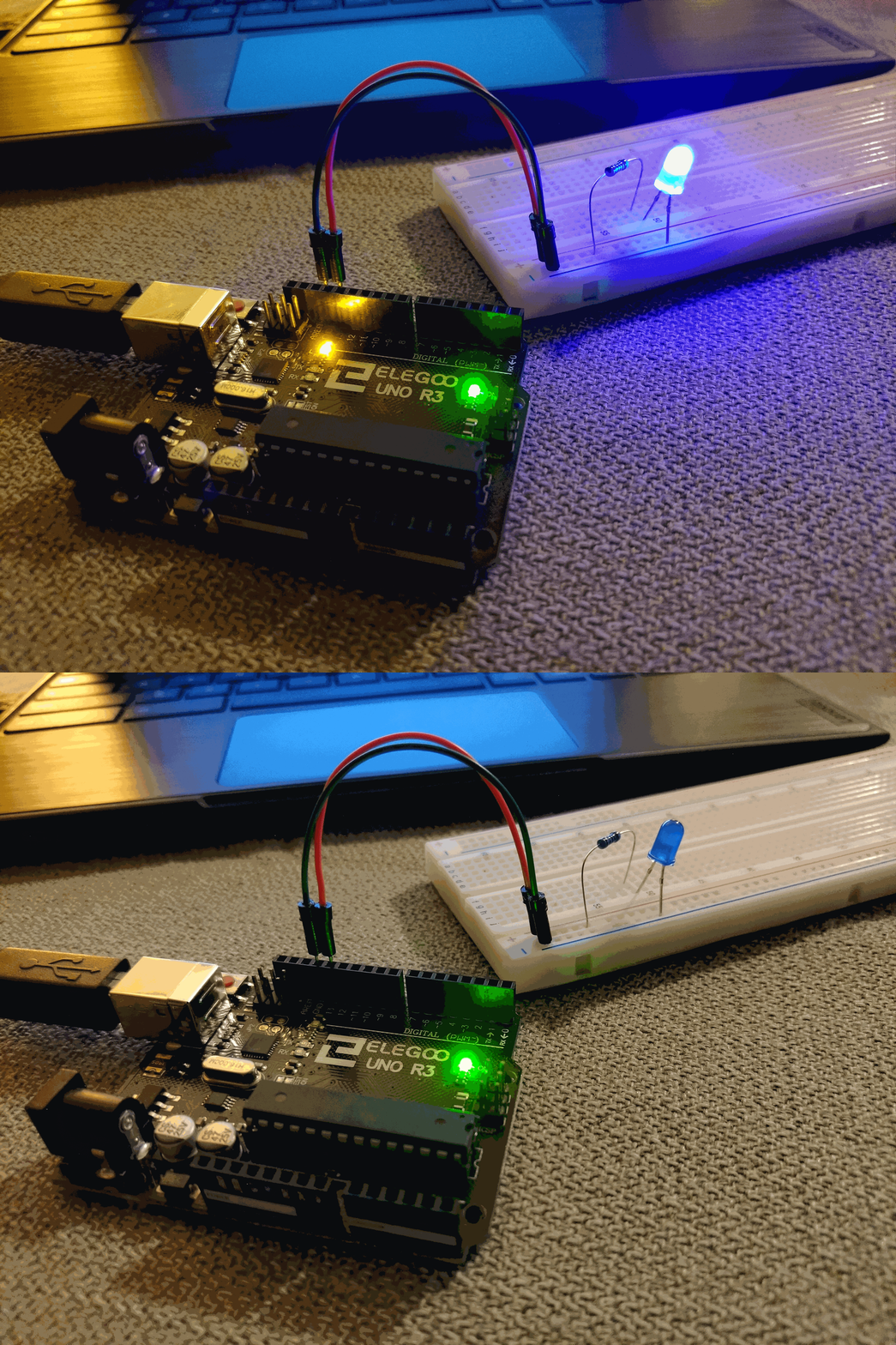
Lets learn how to control an LED that is not built into our board. We will make one of the LEDs in our starter kit light up along with the LED on our board:
To do this we are going to need five items out of our Arduino starter kit:
1) The breadboard
2) An LED (Pick any color you want, make sure it is an LED with only two legs/wires coming out of it)
3) A 1k resistor
4/5) Two wires (preferably one red and one black)
We need to fill in some background information about what these components are in order to understand how to use them. Right about now is a good time to bring up something about the Arduino starter kit, especially if it was handed directly to you from one of us coaches or mentors: The starter kit comes with a complete 176 page tutorial that covers how to use every component that came in your kit. Usually this tutorial document comes on a CD-ROM, if I gave you the kit directly chances are I already took the CD out of the kit. Its not like there is a CD-ROM drive in your Chromebook anyways, right?
So, am I going to re-write the entire tutorial that came with the kit here on this website? Of course not. I had to write the first part of this series because the first three chapters of the tutorial give you instructions on how to use an Arduino with a Windows or Mac computer. We needed instructions for programming Arduino via your Chromebook, but now that you are getting to the point where you can write and upload code and get it from your Chromebook onto your board pretty soon here we are going to start referring you to the tutorial that came with the kit (to save my fingers from getting tired of typing!)
The tutorial that came with the kit does a nice job of talking about the parts we need to use for this lesson, so I’m going to copy and paste that here. So far I have been modifying their lessons slightly, and in the case of running this external LED I am doing the same thing, so don’t worry about the first part of the first page talking about a slightly different list of components. Please read through the pages to get an initial understanding of the components we are using, and then come back here to this page to continue the lesson after reading through it:
Ok, have you downloaded and read the except from the starter kit’s tutorial? Then lets move on.
The last part of the document was talking about resistors. Resistors serve a very important purpose in electronics, but other than using them for our Arduino lessons you won’t often need to mess with them much once you start programming an FRC Robot. You won’t be using many LEDs either, for that matter.
Indeed, if you look through your box of parts in your starter kit there are many things in it that you will probably never use on a competition robot (such as the temperature sensor). Even though not all of these components have a direct use in building an FRC robot, I still want you to learn about most of them because what we are trying to do here is to lay the groundwork and base knowledge of programming a board to use various components.
Just because you may never use a temperature sensor on on a competition robot doesn’t mean that knowledge won’t be useful down the road. You may eventually need to use a similar sensor, perhaps a color sensor, and many of these thing work in a similar fashion so just keep that in mind as you continue through these lessons.
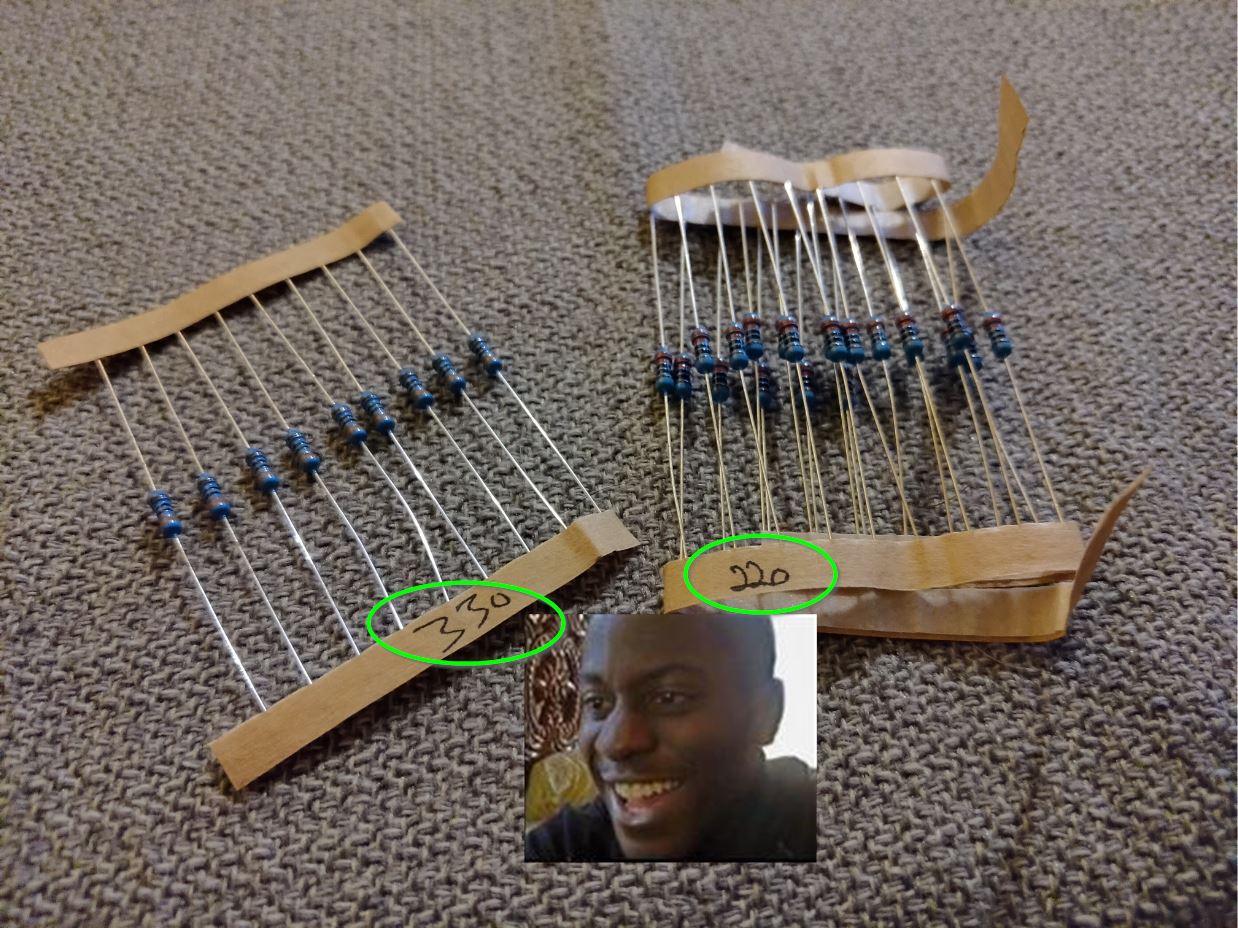
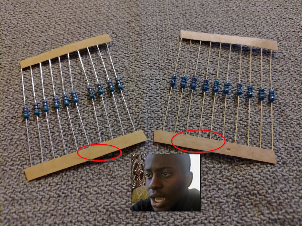
Anyways, back to resistors, they send about a gazillion of those tiny things in your starter kit. Depending on what year it is and what the situation is, there are about three possibilities of the status of the resistors in your particular kit:
- It might be a brand new kit AND the packs of resistors are labeled with their values:
2. It might also be that you have a brand new kit, but the packs of resistors are NOT labeled:
3. Worse than that, you might just get a used kit in which the resistors are laying loose all over the box….
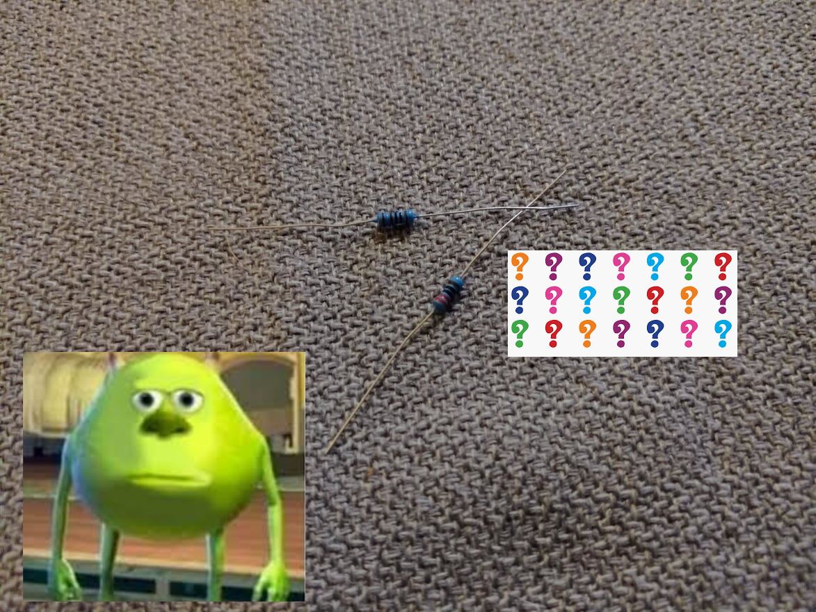
Now, they do send you this nice color chart in the kit (hopefully its still in there if you have a used kit) which can help you determine the values of the resistors:
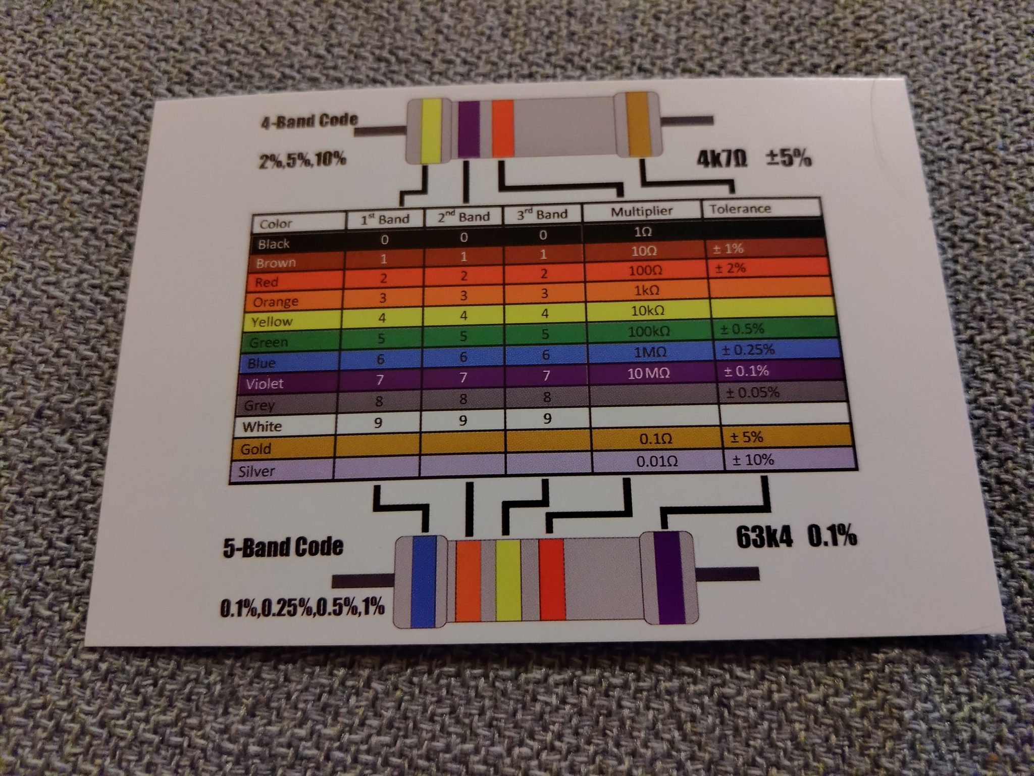
But even still… we are trying to focus on the programming aspect and getting you up to speed so you can work on the actual robot. We already said you won’t have to mess with resistors much on the actual robot, so basically if you don’t get a nice set of resistors that are already labeled for you and ready to go, feel free to reach out to your coach or mentor and see if they can help you out there. If you feel like learning enough about resistors to figure it out on your own, go for it, but this is one area where we don’t need to get too terribly deep into it to get you the knowledge you need to move forward.
If you are going to be turning in your kit at the end of the season please keep the organization of the resistors in mind for the next person who will need to use the kit. Everything else in the kit is fairly distinctive but all the resistors look the same so try not to get them all mixed up and disorganized.
All you need right now is one resistor that is at least 220 ohms, but preferably 1k.
Now, on to hooking up these parts.
The short explanation is that to use an LED, you must also use a resistor to limit the electrical current to avoid burning out the LED. We don’t want to be burning up our parts! The tutorial wants you to hook the LED up according to the diagram and schematics below. This is fine if you want to follow that to start with, but what they are having you do is hook the LED up to direct power off the board. Thats ok to start with but right afterwards we are going to make a small tweak to their layout.
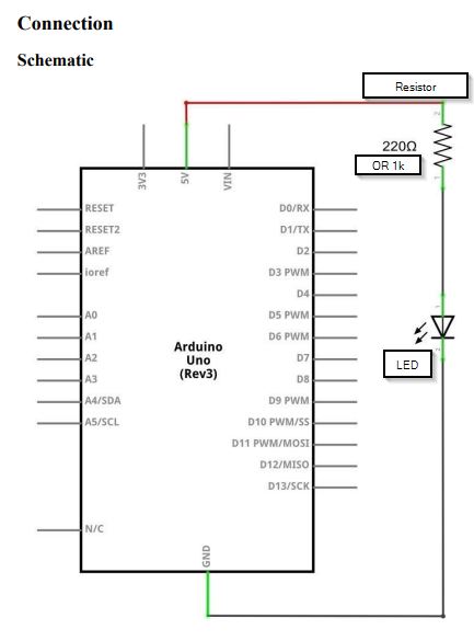
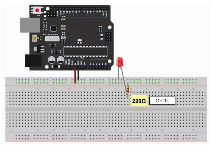
A description from page 41 of the stock tutorial:
The UNO is a convenient source of 5 volts, which we will use to provide power to the LED and the resistor.
Arduino Starter Kit Stock Tutorial, page 41
You do not need to do anything with your UNO, except to plug it into a USB cable. With the 220 Ω resistor in place, the LED should be quite bright. If you swap out the 220 Ω resistor for the 1kΩ resistor, then the LED will appear a little dimmer. Finally, with the 10 kΩ resistor in place, the LED will be just about visible.
Pull the red jumper lead out of the breadboard and touch it into the hole and remove it, so that it acts like a switch. You should just be able to notice the difference.
At the moment, you have 5V going to one leg of the resistor, the other leg of the resistor going to the positive side of the LED and the other side of the LED going to GND. However, if we moved the resistor so that it came after the LED, as shown below, the LED will still light. You will probably want to put the 1kΩ resistor back in place. It does not matter which side of the LED we put the resistor, as long as it is there somewhere
The above is fine, but assuming your Arduino is still running the same Blink sketch from the previous lesson I’d rather have you wire up your LED to pin 13 (and you can use the ground (GND) pin right next to it, all the GND pins on the board are the same) like this:
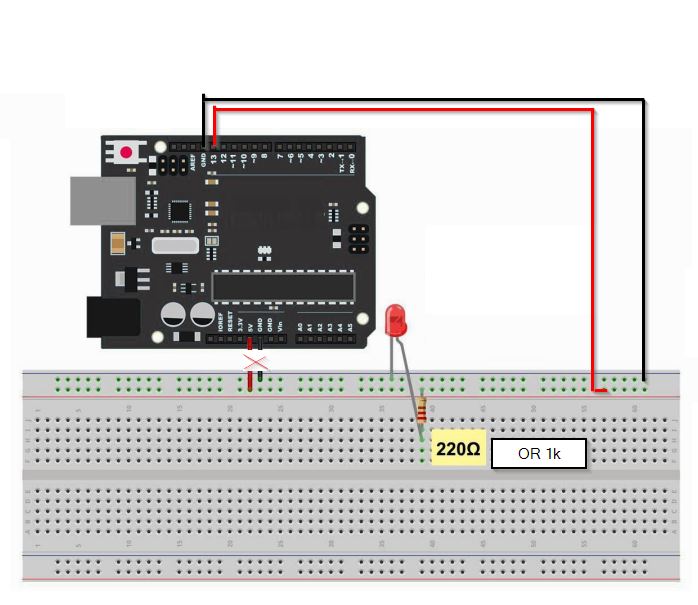
Pin 13 is wired to BOTH the built-in LED on the board and the pin slot #13 on the board itself, so if you wire up your LED to it you should see the built-in LED and your breadboard LED flash together like this:

Self-guided Experiment:
Something to try on your own now: What would you need to do to your code if you wanted to power the breadboard LED from pin 12 instead of pin 13? Try it now.
Hint: You only need to change one thing on line # 10…
All good so far with putting an LED on your breadboard and turning it on and off with your code? If so, you are ready to move on to the next section. If you are having difficulties, please chat with your coach or mentor to get over any humps before moving on.

