Intro to Arduino – Part 9 – Temp Sensor and Serial Monitor

Made your way through all the previous sections? Well done! You are well on your way towards programming for the robotics team, not to mention being able to program an Arduino for yourself and any side projects you want to tackle!

In this section we are going to use the temperature sensor from the kit, and more importantly than that we are going to learn about something called the serial monitor.

You already understand that your Chromebook is sending your code into your Arduino board over the USB cable, but that is not all that the USB connection is good for. The Arduino can actually send messages and data back to your Chromebook over the USB cable as well. This capability is what we are going to leverage to get the temperature readings from the sensor back to your Chromebook. This way we don’t have to hook up an LCD screen to the Arduino just to get some readings from a sensor.

Lets start with the usual steps, download the pages from chapter 9 of the starter kit tutorial here and load up the code below:

Code:

#include "DHT.h"

#define DHTPIN 2     // what pin we're connected to

#define DHTTYPE DHT11   // DHT 11 (there are other types we could be using, such as DHT22)

// Initialize DHT sensor for normal 16mhz Arduino
DHT dht(DHTPIN, DHTTYPE);

void setup() {
  Serial.begin(9600); 
  Serial.println("DHTxx test!");
 
  dht.begin();
}

void loop() {
  // Wait a few seconds between measurements.
  delay(2000);

  // Reading temperature or humidity takes about 250 milliseconds!
  // Sensor readings may also be up to 2 seconds 'old' (its a very slow sensor)
  float h = dht.readHumidity();
  // Read temperature as Celsius
  float t = dht.readTemperature();
  // Read temperature as Fahrenheit
  float f = dht.readTemperature(true);
  
  // Check if any reads failed and exit early (to try again).
  if (isnan(h) || isnan(t) || isnan(f)) {
    Serial.println("Failed to read from DHT sensor!");
    return;
  }

  // Compute heat index
  // Must send in temp in Fahrenheit!
  float hi = dht.computeHeatIndex(f, h);

  Serial.print("Humidity: "); 
  Serial.print(h);
  Serial.print(" %\t");
  Serial.print("Temperature: "); 
  Serial.print(t);
  Serial.print(" *C ");
  Serial.print(f);
  Serial.print(" *F\t");
  Serial.print("Heat index: ");
  Serial.print(hi);
  Serial.println(" *F");
}

Like with the passive buzzer, you will notice at the top of the code that we are using a library to help us use the sensor. Thanks to this library we do not have to read and interpret the raw bits of data the sensor puts out. This makes things easier for us and keeps our code neat and tidy, and easier to understand.

Opening the serial monitor is slightly different in codebender than it is for the IDE used in the tutorial, but its still very easy. Click on the “Serial Monitor” button in the upper right-hand corner of the codebender page and then click on “Connect” in the window that opens up in the lower half of the page.
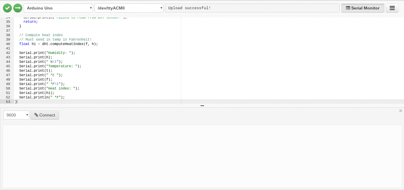
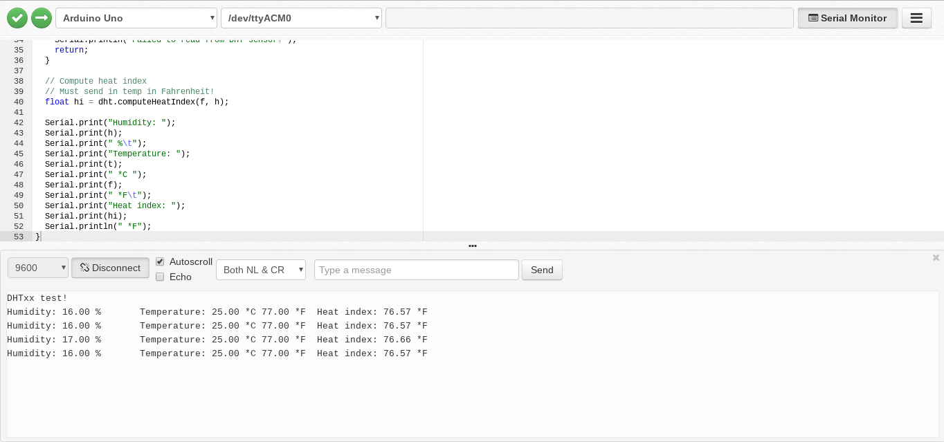
Once successfully connected the serial monitor will start displaying the messages that your Arduino code is sending back over the USB cable, as shown above.

Note that in our setup function we have to initialize the usage of the serial monitor with “Serial.begin(9600);” This sets up the serial connection to send data back to the Chromebook.

Try playing around with the code to change the output coming back to the serial monitor. Try putting the temperature first, and then the humidity. Try removing the heat index portion (what is that anyways?)

Notice that in the serial monitor there is a box where you can type and send a message back to the Arduino. Yes, this is a two-way communication street. It is possible to do things such as turning an LED on and off by sending a message over the serial interface, and sometimes this is easier than wiring in a button.

The serial monitor is very handy for sending back complex data that is difficult for the Arduino to display without a screen, and also handy for debugging code to find problem spots.

Not every type of code and chip you will ever use will communicate via a serial interface, but most will have some kind of text output that will be similar to this which you can use to read and debug data.

When you are done with this section we can make our way to the next part, in which we get to use one of my favorite components: the servo motor.

Intro to Arduino – Part 8 – Buzzers

In this section we will chew through two chapters from the Arduino starter kit’s tutorial, using two different kinds of buzzers.

Download the pages of chapter 7 from the tutorial here:

Code for chapter 7:


int buzzer = 12;//the pin of the active buzzer
void setup()
{
 pinMode(buzzer,OUTPUT);//initialize the buzzer pin as an output
}
void loop()
{
 unsigned char i;
 while(1)
 {
   //output an frequency
   for(i=0;i<80;i++)
   {
    digitalWrite(buzzer,HIGH);
    delay(1);//wait for 1ms
    digitalWrite(buzzer,LOW);
    delay(1);//wait for 1ms
    }
    //output another frequency
     for(i=0;i<100;i++)
      {
        digitalWrite(buzzer,HIGH);
        delay(2);//wait for 2ms
        digitalWrite(buzzer,LOW);
        delay(2);//wait for 2ms
      }
  }
} 

Too easy? Next up we will use a passive buzzer, which has a bit of a curve-ball to it…

Libraries

It should come as no surprise that some components are trickier to control than others. Turning a single LED on and off is relatively straightforward, controlling an LCD display or sending a picture to some kind of TV or monitor is significantly more complex.

Many times there are libraries out there that can make it easier for us to use more complicated parts.

To use the passive version of the buzzer, we will use a library somebody else was nice enough to put together for us. Libraries are typically referenced at the start of your Arduino sketch/code, as shown at the top of the passive buzzer code for chapter 8 below:


#include "pitches.h"
 
// notes in the melody:
int melody[] = {
  NOTE_C5, NOTE_D5, NOTE_E5, NOTE_F5, NOTE_G5, NOTE_A5, NOTE_B5, NOTE_C6};
int duration = 500;  // 500 miliseconds
 
void setup() {
 
}
 
void loop() {  
  for (int thisNote = 0; thisNote < 8; thisNote++) {
    // pin8 output the voice, every scale is 0.5 sencond
    tone(8, melody[thisNote], duration);
     
    // Output the voice after several minutes
    delay(1000);
  }
   
  // restart after two seconds 
  delay(2000);
}

pitches.h” is the library we are pulling in to help us control the passive buzzer. When programming for robotics you will use many libraries from external sources to help you use common components such as servos and sensors. It would be unrealistic to write the code to control something like a color sensor from scratch, at least at this point in your programming career.

codebender is really doing a lot of swell work for us here, because “pitches.h” is already in its internal collection of libraries and it already knows where to get it just by referencing it at the top of our program. Don’t get too used to this, most of the time you have to hunt down the library yourself and pull it into your code project in a much more manual fashion, but we’ll enjoy this while it lasts.

So you have the code for chapter 8 above, here are the pages for chapter 8 from the tutorial:

As usual, follow the steps to set up the component on your breadboard and load up the code to make it run.

We are relying on codebender keeping a compatible version of the “pitches” library on hand so let us know if you run into any problems.

If your musical buzzer is now working, try playing with the code a little to change the tune and see what you can come up with.

Once you’ve had your fun with that, in the next section we are going to play with the temperature sensor in the kit, and learn about the serial monitor.

Intro to Arduino – Part 7 – Tilt Switch

Similar to a button, a tilt-switch is a type of input that can tell our board when a certain condition has occurred. Unlike a button, however, a tilt switch is much more likely to be found on the bot itself rather than on a controller.

Just like the previous chapter, download the material from the Arduino starer kit tutorial here, follow the steps, and use the code below.

Code:


/*****************************************/
const int ledPin = 13;//the led attach to

void setup()
{ 
  pinMode(ledPin,OUTPUT);//initialize the ledPin as an output
  pinMode(2,INPUT);
  digitalWrite(2, HIGH);
} 
/******************************************/
void loop() 
{  
  int digitalVal = digitalRead(2);
  if(HIGH == digitalVal)
  {
    digitalWrite(ledPin,LOW);//turn the led off
  }
  else
  {
    digitalWrite(ledPin,HIGH);//turn the led on 
  }
}
/**********************************************/

Got this one down? Reach out for help if you need it. Don’t forget to really read the code that is being provided and try to understand how it works, ask your coach or mentors questions as you go along.

We are covering a lot and glazing over many details here. The goal is to balance on a fine line between throwing too much info at you vs laying a workable foundation of coding knowledge. You aren’t going to learn everything you need to be a programmer with just these tutorials alone, but you will learn enough to be dangerous and branch out from there.

When you are ready head to the next section where we will cover a couple chapters of the starter kit’s tutorial on buzzers.

Intro to Arduino – Part 6 – Using Buttons

In this part of the tutorial that came with the Arduino starter kit they are going to show you how to use buttons to turn one of your LEDs on and off.

Using buttons is a critical part of programming a robot for the robotics competition. The driver will need to use buttons on the joystick or controller to tell the robot to do certain things (such as picking up a game piece or throwing a ball). Right now we are still keeping things bite-sized and simple; today we turn an LED on and off on-demand, but soon you will be programming your team’s bots to do awesome things!

Please download and read through chapter 5 from the tutorial and follow the steps as you did for the previous chapter:

Again, when you get to the code section copy and paste the code below into a blank codebender window and upload it to your Arduino:


int ledPin = 5;
int buttonApin = 9;
int buttonBpin = 8;

byte leds = 0;

void setup() 
{
  pinMode(ledPin, OUTPUT);
  pinMode(buttonApin, INPUT_PULLUP);  
  pinMode(buttonBpin, INPUT_PULLUP);  
}

void loop() 
{
  if (digitalRead(buttonApin) == LOW)
  {
    digitalWrite(ledPin, HIGH);
  }
  if (digitalRead(buttonBpin) == LOW)
  {
    digitalWrite(ledPin, LOW);
  }
}

If this went well, you are cruising! Speed bumps do occur though, so if you run into any along the way bring your project to your coach or mentor and we’ll take a look together to see where its going awry.

Chances are you will not be creating a set of buttons from scratch like this for your driver to control the robot with. It is much more likely that you will be writing code to react to buttons on an xBox controller or joystick, but the principles are the same.

Its also possible that a button, or something very similar to a button, may be installed on the robot itself to trigger certain things. For example, perhaps when the robot drives into a wall a button on the front of the robot may be pressed which causes the robot to back up. Or perhaps when a ball falls into a certain location, the ball may hit a button that causes the ball to be thrown into the air.

Once you are ready, head to the next lesson to learn about a cousin of the button called the tilt switch.

Intro to Arduino – Part 5 – RGB LED and Moving into the Kit’s Tutorial

Ok, we are getting close to the point where you can get pretty much your entire lesson out of the tutorial document that came with your starter kit. In chapter 4 of the stock tutorial doc they teach you how to use another, much cooler type of LED that can display different colors.

There are going to be some slight differences still because you are working on a Chromebook using codebender to write and upload your code, while the document is going to be referencing a windows computer using a different code editor. Most of the steps are the same.

To complete this section I have a copy of chapter 4 from the stock tutorial for you to download here:

You will download this and go through the steps and instructions contained within.

When you get to the part where they talk about the code for this chapter, copy and paste this code below into an empty codebender window and upload it to your Arduino:

// Define Pins
#define BLUE 3
#define GREEN 5
#define RED 6

void setup()
{
pinMode(RED, OUTPUT);
pinMode(GREEN, OUTPUT);
pinMode(BLUE, OUTPUT);
digitalWrite(RED, HIGH);
digitalWrite(GREEN, LOW);
digitalWrite(BLUE, LOW);
}

// define variables
int redValue;
int greenValue;
int blueValue;

// main loop
void loop()
{
#define delayTime 10 // fading time between colors

redValue = 255; // choose a value between 1 and 255 to change the color.
greenValue = 0;
blueValue = 0;

// this is unnecessary as we've either turned on RED in SETUP
// or in the previous loop ... regardless, this turns RED off
// analogWrite(RED, 0);
// delay(1000);

for(int i = 0; i < 255; i += 1) // fades out red bring green full when i=255
{
redValue -= 1;
greenValue += 1;
// The following was reversed, counting in the wrong directions
// analogWrite(RED, 255 - redValue);
// analogWrite(GREEN, 255 - greenValue);
analogWrite(RED, redValue);
analogWrite(GREEN, greenValue);
delay(delayTime);
}

redValue = 0;
greenValue = 255;
blueValue = 0;

for(int i = 0; i < 255; i += 1) // fades out green bring blue full when i=255
{
greenValue -= 1;
blueValue += 1;
// The following was reversed, counting in the wrong directions
// analogWrite(GREEN, 255 - greenValue);
// analogWrite(BLUE, 255 - blueValue);
analogWrite(GREEN, greenValue);
analogWrite(BLUE, blueValue);
delay(delayTime);
}

redValue = 0;
greenValue = 0;
blueValue = 255;

for(int i = 0; i < 255; i += 1) // fades out blue bring red full when i=255
{
// The following code has been rearranged to match the other two similar sections
blueValue -= 1;
redValue += 1;
// The following was reversed, counting in the wrong directions
// analogWrite(BLUE, 255 - blueValue);
// analogWrite(RED, 255 - redValue);
analogWrite(BLUE, blueValue);
analogWrite(RED, redValue);
delay(delayTime);
}
}

If you get it working, you are doing great! If you run into problems, don’t be too discouraged. Check in with your coach or mentor to iron out any issues with your wiring and to make sure the code is working properly.

Once you get the RGB LED working, take a closer look at the code that was provided to control it. Feel free to change and tweak some things to see if you can change the speed or behavior of the code as we have done before with the board’s built-in LED.

Make note on any of the confusing parts of the code and ask your coach or mentor to help explain how certain sections work.

Once you are comfortable with this section you can move on to the next section where we will learn how to use buttons to control things.

Intro to Arduino – Part 4 – Control an External LED

Ready to start hooking stuff from the kit up to your board and making them do things? Great!

Lets learn how to control an LED that is not built into our board. We will make one of the LEDs in our starter kit light up along with the LED on our board:

To do this we are going to need five items out of our Arduino starter kit:
1) The breadboard
2) An LED (Pick any color you want, make sure it is an LED with only two legs/wires coming out of it)
3) A 1k resistor
4/5) Two wires (preferably one red and one black)

We need to fill in some background information about what these components are in order to understand how to use them. Right about now is a good time to bring up something about the Arduino starter kit, especially if it was handed directly to you from one of us coaches or mentors: The starter kit comes with a complete 176 page tutorial that covers how to use every component that came in your kit. Usually this tutorial document comes on a CD-ROM, if I gave you the kit directly chances are I already took the CD out of the kit. Its not like there is a CD-ROM drive in your Chromebook anyways, right?

So, am I going to re-write the entire tutorial that came with the kit here on this website? Of course not. I had to write the first part of this series because the first three chapters of the tutorial give you instructions on how to use an Arduino with a Windows or Mac computer. We needed instructions for programming Arduino via your Chromebook, but now that you are getting to the point where you can write and upload code and get it from your Chromebook onto your board pretty soon here we are going to start referring you to the tutorial that came with the kit (to save my fingers from getting tired of typing!)

The tutorial that came with the kit does a nice job of talking about the parts we need to use for this lesson, so I’m going to copy and paste that here. So far I have been modifying their lessons slightly, and in the case of running this external LED I am doing the same thing, so don’t worry about the first part of the first page talking about a slightly different list of components. Please read through the pages to get an initial understanding of the components we are using, and then come back here to this page to continue the lesson after reading through it:

Ok, have you downloaded and read the except from the starter kit’s tutorial? Then lets move on.

The last part of the document was talking about resistors. Resistors serve a very important purpose in electronics, but other than using them for our Arduino lessons you won’t often need to mess with them much once you start programming an FRC Robot. You won’t be using many LEDs either, for that matter.

Indeed, if you look through your box of parts in your starter kit there are many things in it that you will probably never use on a competition robot (such as the temperature sensor). Even though not all of these components have a direct use in building an FRC robot, I still want you to learn about most of them because what we are trying to do here is to lay the groundwork and base knowledge of programming a board to use various components.

Just because you may never use a temperature sensor on on a competition robot doesn’t mean that knowledge won’t be useful down the road. You may eventually need to use a similar sensor, perhaps a color sensor, and many of these thing work in a similar fashion so just keep that in mind as you continue through these lessons.

Anyways, back to resistors, they send about a gazillion of those tiny things in your starter kit. Depending on what year it is and what the situation is, there are about three possibilities of the status of the resistors in your particular kit:

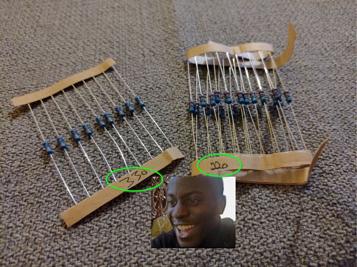
  1. It might be a brand new kit AND the packs of resistors are labeled with their values:

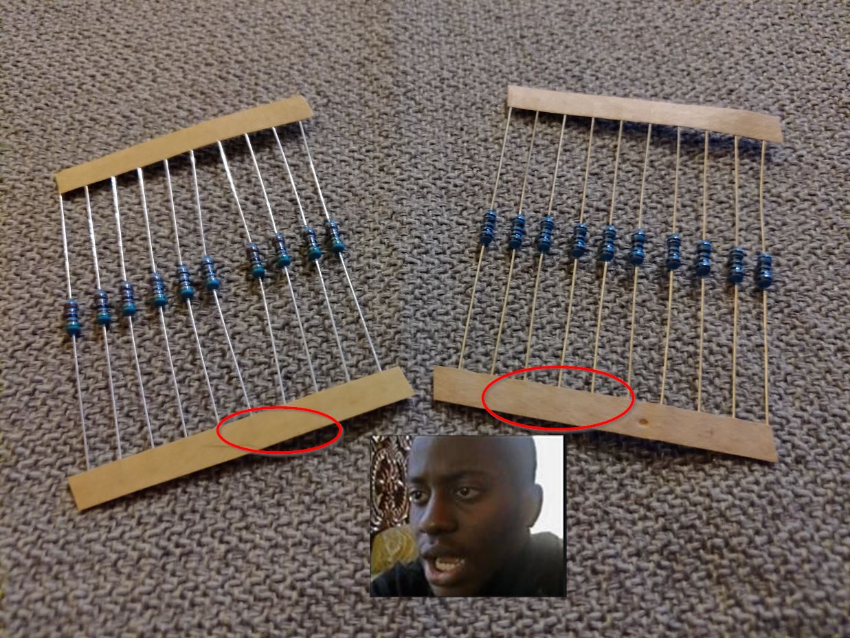
2. It might also be that you have a brand new kit, but the packs of resistors are NOT labeled:

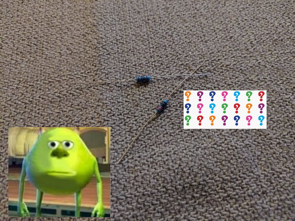
3. Worse than that, you might just get a used kit in which the resistors are laying loose all over the box….

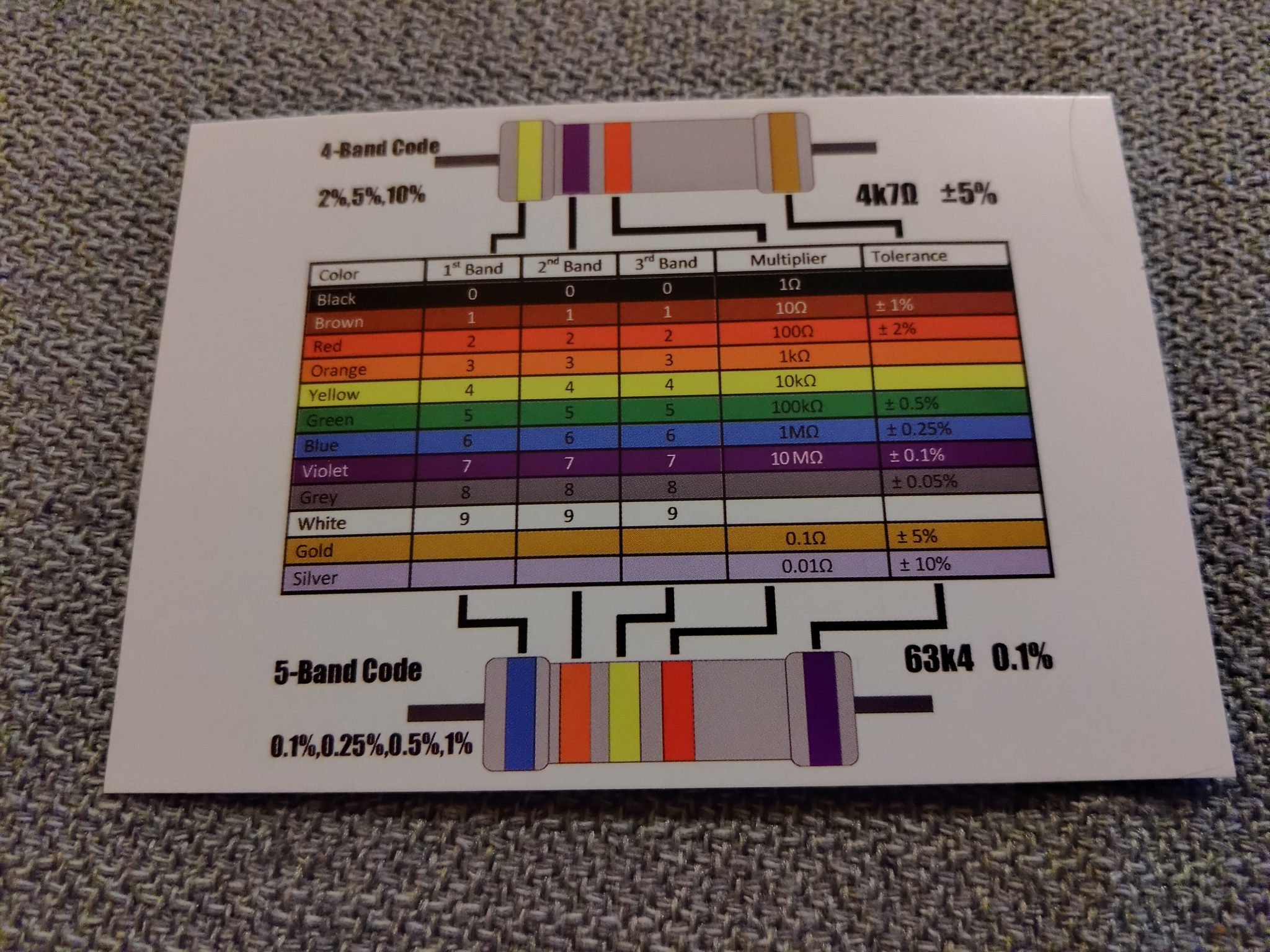
Now, they do send you this nice color chart in the kit (hopefully its still in there if you have a used kit) which can help you determine the values of the resistors:

But even still… we are trying to focus on the programming aspect and getting you up to speed so you can work on the actual robot. We already said you won’t have to mess with resistors much on the actual robot, so basically if you don’t get a nice set of resistors that are already labeled for you and ready to go, feel free to reach out to your coach or mentor and see if they can help you out there. If you feel like learning enough about resistors to figure it out on your own, go for it, but this is one area where we don’t need to get too terribly deep into it to get you the knowledge you need to move forward.

If you are going to be turning in your kit at the end of the season please keep the organization of the resistors in mind for the next person who will need to use the kit. Everything else in the kit is fairly distinctive but all the resistors look the same so try not to get them all mixed up and disorganized.

All you need right now is one resistor that is at least 220 ohms, but preferably 1k.

Now, on to hooking up these parts.

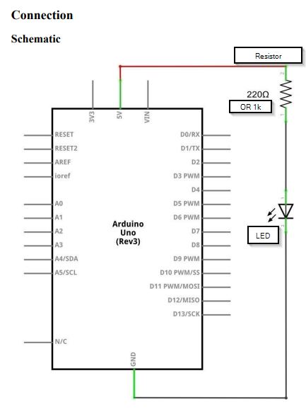
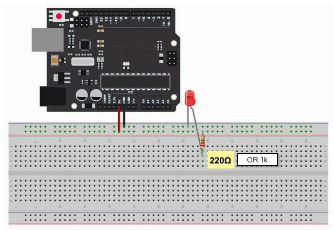
The short explanation is that to use an LED, you must also use a resistor to limit the electrical current to avoid burning out the LED. We don’t want to be burning up our parts! The tutorial wants you to hook the LED up according to the diagram and schematics below. This is fine if you want to follow that to start with, but what they are having you do is hook the LED up to direct power off the board. Thats ok to start with but right afterwards we are going to make a small tweak to their layout.

A description from page 41 of the stock tutorial:

The UNO is a convenient source of 5 volts, which we will use to provide power to the LED and the resistor.

You do not need to do anything with your UNO, except to plug it into a USB cable. With the 220 Ω resistor in place, the LED should be quite bright. If you swap out the 220 Ω resistor for the 1kΩ resistor, then the LED will appear a little dimmer. Finally, with the 10 kΩ resistor in place, the LED will be just about visible.

Pull the red jumper lead out of the breadboard and touch it into the hole and remove it, so that it acts like a switch. You should just be able to notice the difference.

At the moment, you have 5V going to one leg of the resistor, the other leg of the resistor going to the positive side of the LED and the other side of the LED going to GND. However, if we moved the resistor so that it came after the LED, as shown below, the LED will still light. You will probably want to put the 1kΩ resistor back in place. It does not matter which side of the LED we put the resistor, as long as it is there somewhere

Arduino Starter Kit Stock Tutorial, page 41

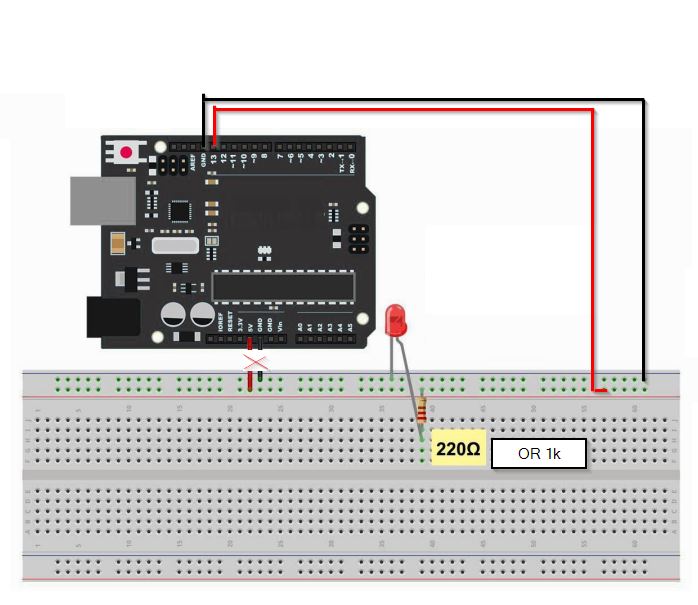
The above is fine, but assuming your Arduino is still running the same Blink sketch from the previous lesson I’d rather have you wire up your LED to pin 13 (and you can use the ground (GND) pin right next to it, all the GND pins on the board are the same) like this:

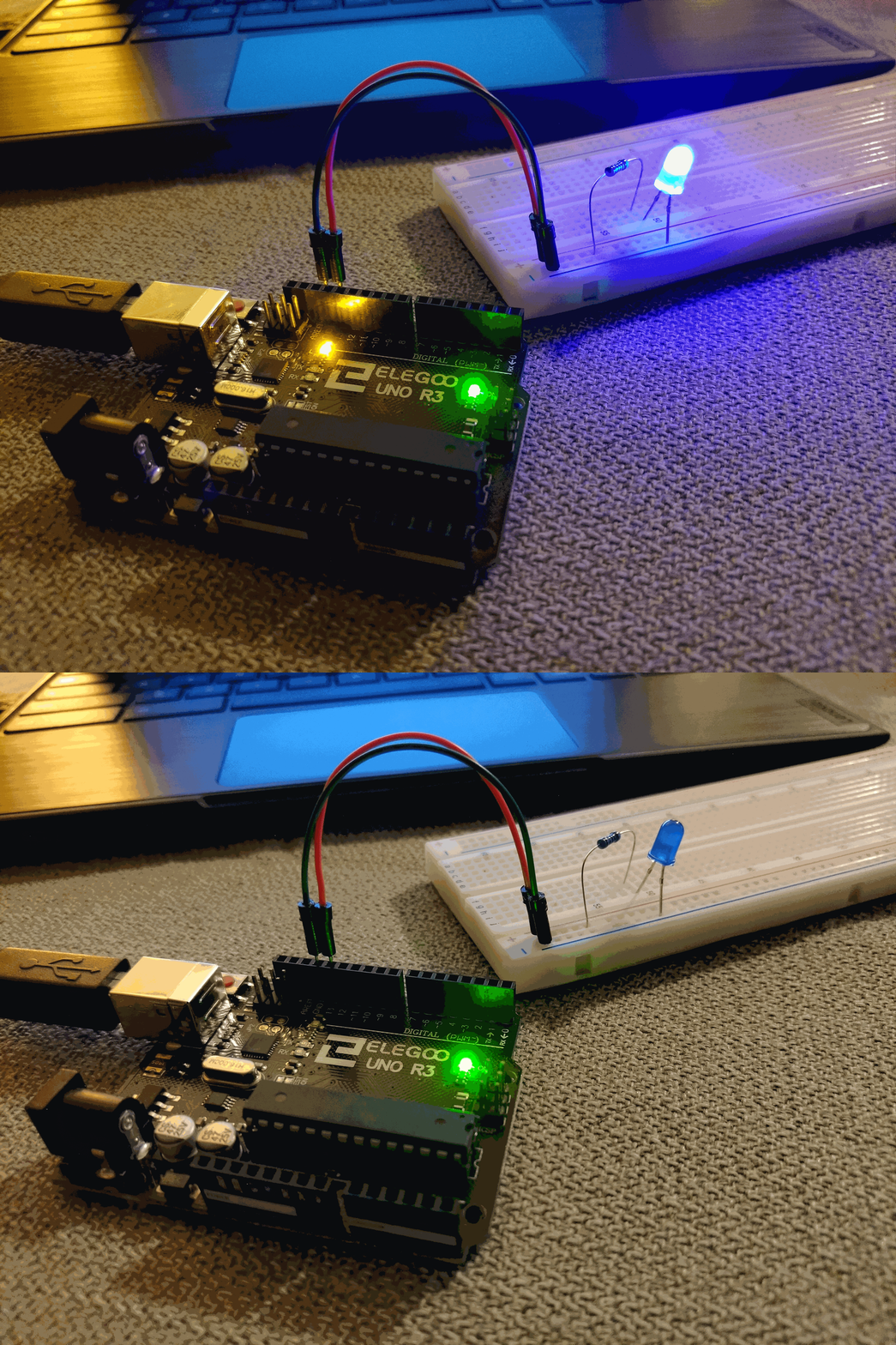
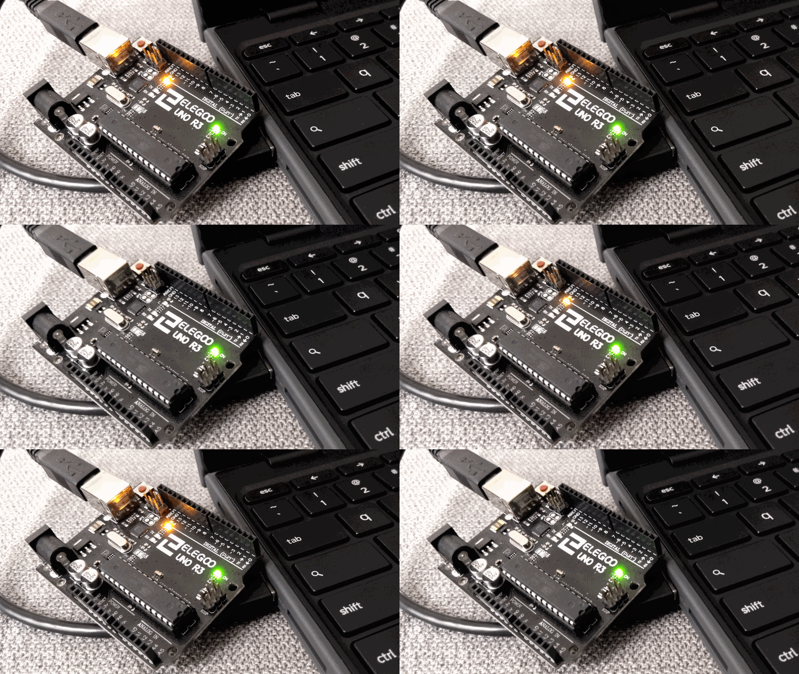
Pin 13 is wired to BOTH the built-in LED on the board and the pin slot #13 on the board itself, so if you wire up your LED to it you should see the built-in LED and your breadboard LED flash together like this:

Self-guided Experiment:

Something to try on your own now: What would you need to do to your code if you wanted to power the breadboard LED from pin 12 instead of pin 13? Try it now.

Hint: You only need to change one thing on line # 10…

All good so far with putting an LED on your breadboard and turning it on and off with your code? If so, you are ready to move on to the next section. If you are having difficulties, please chat with your coach or mentor to get over any humps before moving on.

Intro to Arduino – Part 3 – A closer look at “Blink”

In the previous section of the series we got our programming tools squared away and got our first piece of code uploaded to our Arduino board. We didn’t write this code ourselves, and soon you will find out just how typical it is to start off with a sample or snippet from the internet. Very few people have enough knowledge memorized to simply open up a blank code editor and start spewing out flawless code without any help or external reference.

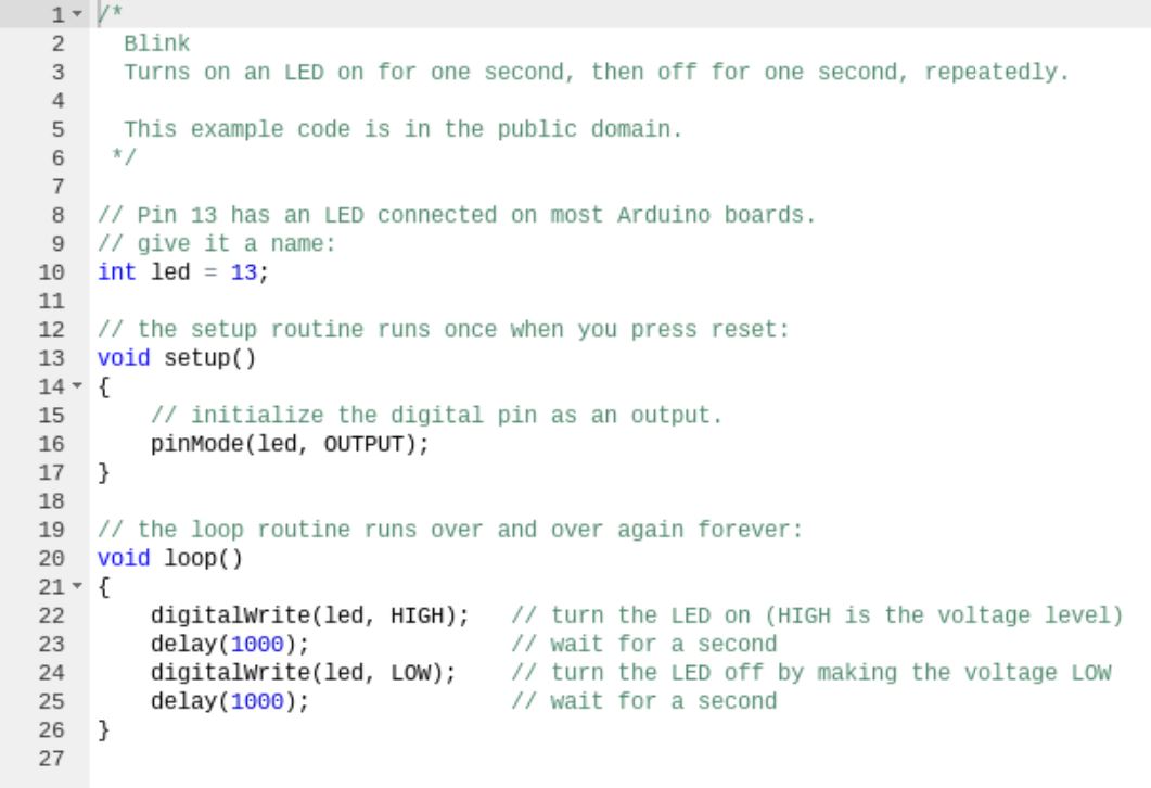
Lets take a closer look at the two dozen or so lines of sample code we uploaded to our board that caused the board’s built-in LED to ‘Blink’:

The green text is what we call “comments”. Comments are not code, rather, they are bits of pieces of information we leave like breadcrumbs for ourselves and others to help describe what a portion of code is doing.

There are two kinds of comments;
A single-line comment begins with two slashes like this: //
A multi-line comment is wrapped with /* and */
The /* is the beginning of the multi-line comment, and the */ is the end.

The // and /**/ tell the compiler to ignore this piece of text because it is not code, its just information we write to ourselves or for other people who will have to read and understand the code later.

So other than the comments, the only *real* code in the whole 26 line file is on lines 10, 13-17, and 20-26.

On Line 10 we are declaring a integer-type variable and setting it to a value of 13.
13 is the number of the pin on our Arduino board that also happens to be connected to the built-in LED. The Arduino Uno has many pins that we can use to connect to more LEDs, motors, sensors, buttons etc to make the Arduino do more stuff.

Line 13 is the start of a critical portion of any Arduino sketch (a sketch is what they call a chunk of code written for Arduino). This line begins the setup function, which is a chunk of code that runs one time when the Arduino board is first powered up. The only code in our setup function is a single pinMode command that tells the board we are going to use pin number 13 as an output (to drive the LED).

From there we get to Line 20, which starts the other critical portion of any Arduino sketch called the loop. The loop is pretty much what it sounds like, a set of commands that the Arduino board will repeat over and over again (forever, or until it is unplugged).

There are only four lines that make up whats happening in our loop, two output writes and two delays. We write a HIGH output to the LED pin, we wait for one second (1000 milliseconds), then we write LOW to the LED pin, and wait another second. This repeats for as long as your board is plugged into power.

Lets change this up a little. In the two lines of the loop that say “delay(1000);” go ahead and change the numbers (the milliseconds of delay) to something else, such as “delay(100);”. After making this change, use the ‘Run on Arduino’ button in the upper left to send the changed code to the board.

The LED is now blinking 10 times faster, because we have shortened the delays from one full second to one-tenth of a second.

Now change the delays to be “delay(20);”
Notice the LED blinks quite fast now.

How about “delay(10);” ?
Now the LED blinks so fast your eye can hardly detect the rapid flickering. The LED is still turning on and off, but its doing it so quickly that to us the LED is more or less just “On”.

This highlights an important concept for you to understand. The loop function happens fast. Very, very fast. Your Arduino Uno can execute roughly 16 million instructions per second. Without putting a delay in between the commands where we turn the LED ON and OFF, we would never stand a chance of seeing the program work with our eyes. Its simply happening way too fast for us to see.

Go ahead and play with some other values for the delay commands. What happens when they are not the same number of milliseconds?

Its handy that our board has a light built-in so that we could play with some code without having to hook anything else up to our board, but we want to learn how to control other things connected to our board. Eventually we need to be able to program things to control motors, sensors, react to buttons and joysticks, etc. So what are we waiting for? Lets move on to the next lesson and look at how we can control our own LED light off the board.

Intro to Arduino – Part 2 – Programming Arduino via Chromebook

As of this writing, the vast majority of Arduino tutorials assume you have a windows or mac computer running the IDE provided by Arduino itself. The students I work with are issued Chromebooks by the school, so the first thing we need to address is how to work with Arduino code in a Chromebook and how to program our Arduino board from the same.

codebender to the rescue!

There is more than one way to program an Arduino board from a Chromebook. The tool I have chosen for our purposes is codebender, an online IDE that works with Chromebooks (and almost any other device that can browse the internet). I’m going with codebender because they have a special education version that makes it even easier to get the students the tools they need without any installation process or complicated setup. Many props to them for providing this tool for our use (I mean, its not free, but I’m still glad they provide it!)

If you are not a student you can use the regular version of codebender. There is a free trial you can get started with to see if you like it, if you don’t feel free to google around for other Arduino IDE tools that work on ChromeOS. The tutorials I’m writing should work with just about any IDE you can find.

STUDENTS: To access the codebender tool from your Chromebook you will need a special link we will provide either in-person or via email/Discord. Make sure you have received this link and are able to open the codebender tool before proceeding. Contact a coach or mentor if you have any issues or still need to get the link.

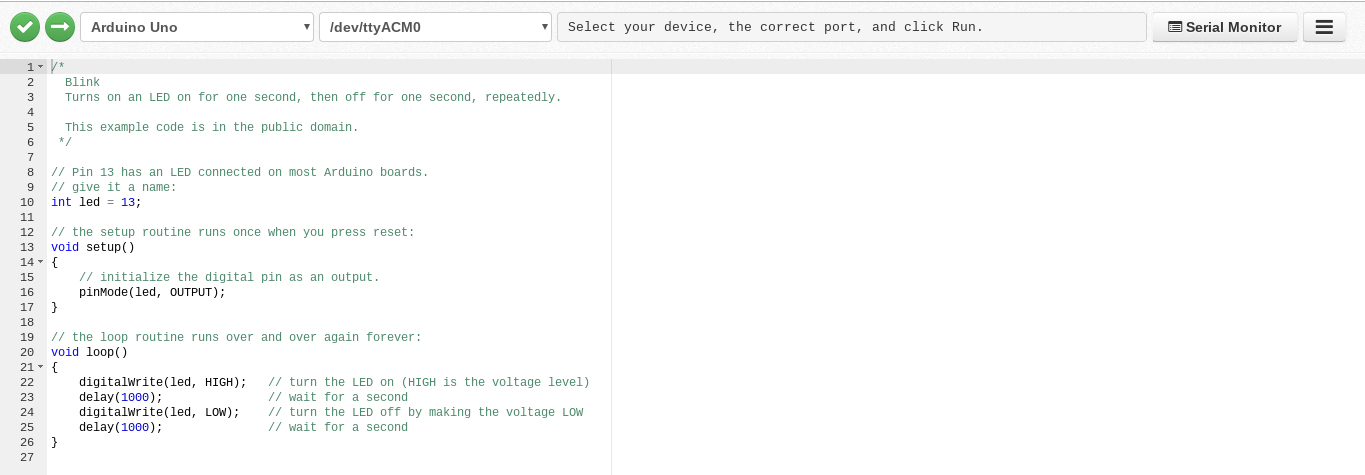
If the link is working for you (or if you are using the regular version of codebender) you should find yourself on a page that looks like the screenshot above. Basically a blank code window ready to use to write code for our Arduino board.

The first thing you will want to do is install the codebender plugin for Chrome. This is what allows the online code editor to detect and push code to your Arduino board.

If you are opening the tool for the first time, there should be a grey bar at the top with a link to click on that will take you to the plugin page. At this time I don’t know for certain if there will be any blocks or issues with that on a student device, talk to your coach or mentor if you run into any issues at this step.

The next thing you will want to do is set the correct board in the upper-left menu.
Almost every Arduino starter kit comes with an Arduino Uno, so most likely this is what you will need to select here:

If you are using any other board (such as a Nano), choose the board that matches whatever you are using.

Next we’re going to load up a little bit of sample code and see if we can get it onto our board. We’ll dive into exactly what this code does in a little bit, but for now lets just see if we can get the code from our Chrombook into the Arduino board.

Open the hamburger menu in the upper-right-hand corner of the editor, hover over “Load Example” and select the “Blink” menu option within. The sample code for the “Blink” sketch should get loaded into the editor window:

Now, in the upper left we have two green buttons that do two important things for us.

“Verify Code”:

This button is used to compile your code and check it for syntax errors. You can click on this button and you should see a message in the grey bar to the right that says “Verification Successful”

And the other button, “Run on Arduino” will actually send your code to your Arduino board.

There is more than one way to do this, but typically we will be programming our boards over a USB cable. Make sure your Arduino board is connected to your Chromebook’s USB port and try to send the “Blink” code to your Arduino now.

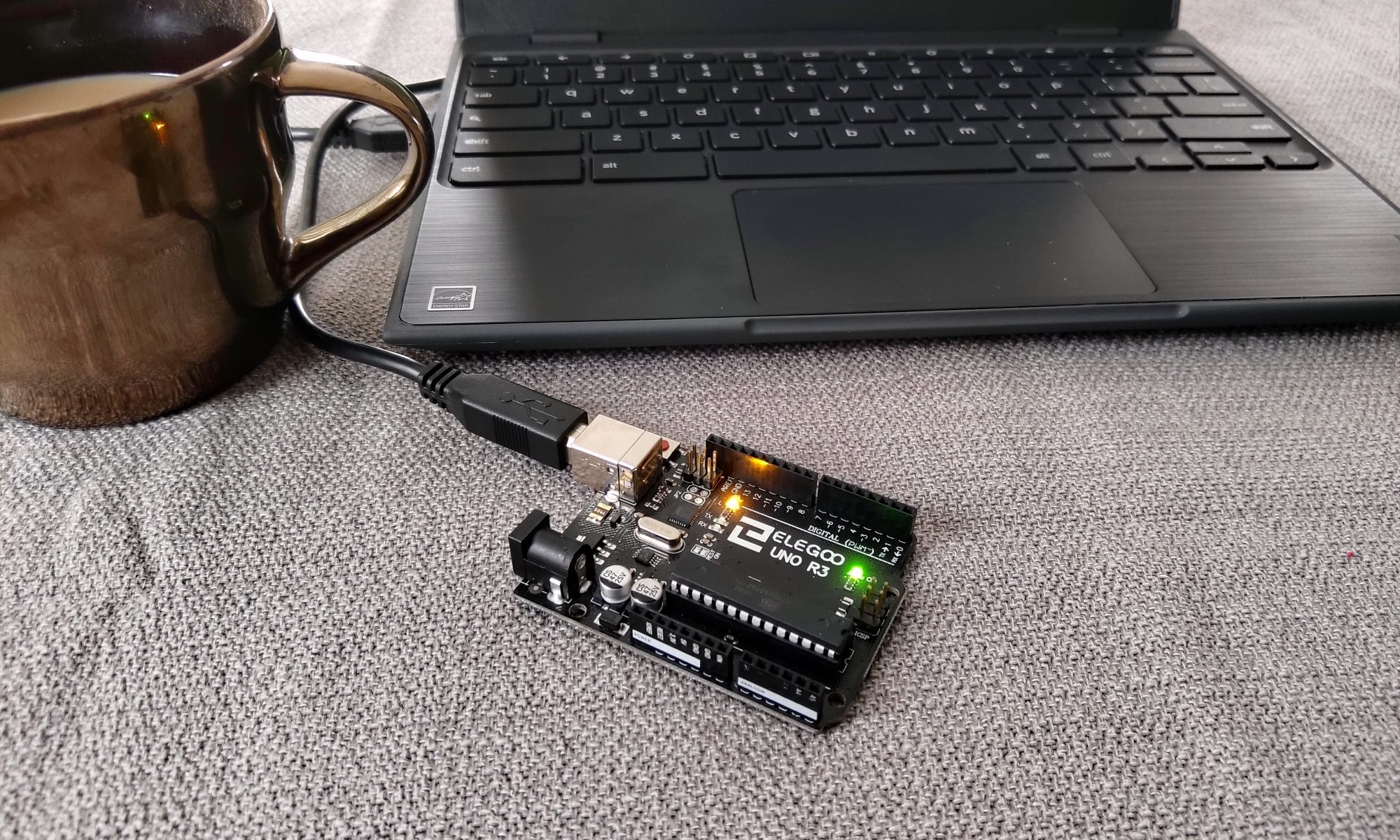
If this works, the message in the grey bar at the top will say “Upload successful!” and the orange or yellow LED light on your Arduino Uno board will begin to blink slowly:

If this is working then our programming tools are set and you are ready to move on to the Arduino code tutorials in the next sections. If you are stuck with some kind of error and the code won’t upload to your board, you can reach out to a couch or mentor for help and/or try googling the issue a bit and see if you can find a solution (especially if its going to be a while before a coach or mentor can check out your setup.)

In the next section we will take a closer look at the “Blink” sample code to learn more about what it does and how it works.

Intro to Arduino – Part 1 – About this Series

Welcome! There are two reasons why you might have ended up on his page. Either you got here from Google (which means my website is doing amazingly well), OR (much more likely) you are a student on the robotics team who got sent here to get started with learning some programming.

That second scenario is going to be the assumption for the following pages in these tutorials. If you are NOT a student who was sent here by direct reference, the tutorials may still be helpful but you should know that a lot of the core material simply comes from the tutorial PDF that comes with almost any Arduino Starter Kit found on Amazon.

The main reasons I’m putting this series together are
1) The students I’m working with in robotics are using Chromebooks, and the tutorial that comes in the starter kits only cover windows/mac/linux.
2) The tutorial in the starter kit is extensive. I want to focus on the portions that are pertinent to robotics and skip over some of the unrelated components in the kit. Later in the series I also want to expand on some components a little further than the base tutorial does.

So what are we trying to accomplish here with our Arduinos? Competition FRC robots are not run by Arduino, so how does learning about these little microchips help us?

Well, you’re likely here because you said you are interested in programming for the robotics team, but you are extremely new to it. Nothing wrong with that. Everyone starts somewhere, but diving straight into competition robot programming from scratch is like starting out learning to swim by putting on deep sea scuba gear.

Programming can often be difficult and discouraging. FIRST Robotics wants their program, coaches, and mentors to encourage and inspire students towards science and technology, not put them off from it. I agree with that goal 100%, and my opinion is that the best way for younger/newer students to start learning about programming related to robotics is with small, bite size examples they can do hands-on at their own pace (with coach and mentor assistance and guidance, of course).

The design and build period for the robotics competition is short and hectic. There is a lot going on and, if your team is going the full-on code route, there is a heck of a lot of code to write. The programming division of the team will need to bring together code to control half a dozen or more motors and components to carry out the game tasks. Without working code, the robot can’t play the game. Without good code, the robot probably can’t play the game well and competitively. Worse yet, if the newest programming students have an overly difficult and stressful time trying to dive directly into advanced programming they may become too discouraged to stick with it.

With that in mind, this series intends to get new students rolling with a customized guide through a standard Arduino starter kit. Arduino programming is very similar to the kind of programming done for a roboRIO on an FRC bot. Once you are comfortable scratching out some code for an Arduino board, you will be in a great spot to make the jump to programming for a roboRIO, and the code you will see the older students making for the roboRIO will start to make more sense.

This is still going to be something of a crash-course, we are going to glaze over some details and nuances here and there for the sake of expediency, and also because the internet is already full of great info and tutorials you can google to your heart’s content (no need for me to recreate the wheel). Please don’t limit yourself only to my tutorials, there is a whole world of great resources out there on the internet.

If you are ready to get started, lets move on to the next post in the series to get familiar with our Arduino kit and learn how we program it from our Chromebooks.